40 electric motor diagram with labels
Three Phase Motor Power & Control Wiring Diagrams A client has two motors which he wants to run them in two modes I, Manual mode Ii, Automatic mode. On the manual mode, motor A and motor B can be controlled separately by selector switch. On the automatic mode, motor A has to run for 3 minute then motor B comes on also. Can you help me with the controlled diagram Electric Motor Controller, 36V/48V 350W Brainpower Motor … Suitable for electric bicycles, scooter, etc. Specification: Material: Aluminium alloy Rated Working Voltage: 36/48V Rated Power: 350W Current: 13A Low Voltage Protection: 31/42V Suitable Motor Phrase Angle: 60 / 120 degree Suitable for: electric bicycle, scooter, etc Size: Approx. 9 x 5.3 x 3cm / 3.5 x 2 x 1.18inch Weight: Approx. 204g Package List: 1 x Brushless Controller
Single Phase Electric Motor Wiring Tutorial: Baldor, WEG, Leeson In this video, Jamie shows you how to read a wiring diagram and the basics of hooking up an electric air compressor motor. These tips can be used on most ele...

Electric motor diagram with labels
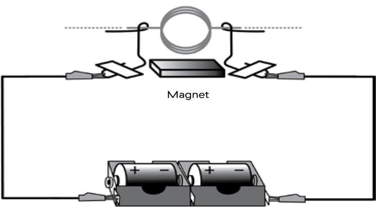
What is an Electric Motor? with the Help of a Labelled Diagram ... An electric motor is a device that converts electrical energy into mechanical energy. Diagram: Electric motor Working of an electric motor: An electric motor works on the principle of magnetic effect of electric current. Parts of Motor, Working of Electric Motor & Uses - BYJUS Take two bar magnets and keep the poles facing each other with a small space in between. Now, take a small length of a conducting wire and make a loop. Keep this loop in between the space between the magnets such that it is still within the sphere of influence of the magnets. Now for the last bit. Connect the ends of the loop to battery terminals. PDF Understanding Electric Motor Nameplates Figure 2 is a view of the underside of an electric motor. The letters are NEMA standard letters and the actual dimensions for general purpose motors are shown in Table 1. The diameter of the bolt hole of the motor mounting bracket is letter H. The diameter is 1/32 of an in. larger than the bolt used for mounting.
Electric motor diagram with labels. Dayton Electric Motors Wiring Diagram Gallery 09.06.2019 · Name: dayton electric motors wiring diagram – marathon electric motor wiring diagram Search and free form templates and tested template designs Download for free for mercial or non; File Type: JPG; Source: canhodatgiaresidence.org; … Generator Automatic Transfer Switch Wiring Diagram Sample 03.05.2020 · Wiring Diagram Sheets Detail: Name: generator automatic transfer switch wiring diagram – How to Install Portable Generator to House Wiring Inspirational Awesome Standby Generator Wiring Diagram Contemporary Everything; File Type: JPG; Source: firedupforkids.org; Size: 80.03 KB; Dimension: 534 x 443; What is a Wiring Diagram? PDF Electrical Symbols and Line Diagrams - University of Florida A line (ladder) diagram is a diagram that shows the logic of an electrical circuit or system using standard symbols. A line diagram is used to show the relationship between circuits and their components but not the actual location of the components. Line diagrams provide a fast, easy understanding of the connections and use of components. Electric Motor Nameplate Details Explained | Electric Motor ... The nameplate shown in Figure 1 indicates the electric motor is rated 1 HP. With a service factor of 1.15, the motor can be overloaded up to 1.15 horsepower. If the motor is operated in the service factor range continuously, it will cause a reduction in motor speed and efficiency, and an increase in the motor's operating temperature.
Electrical Diagrams and Schematics - Inst Tools Types of Electrical Diagrams or Schematics There are three ways to show electrical circuits. They are wiring, schematic, and pictorial diagrams. The two most commonly used are the wiring diagram and the schematic diagram. The uses of these two types of diagrams are compared in Table 1. Dual Voltage Motors, How They Work, And Wiring Them Without ... - YouTube How Dual Voltage Motors Work, and How to Wire them even without the wire labels. I have received several requests to cover this topic. If you want to chip in... What details a motor nameplate shows and how to use them The nameplate for a two-pole 15 kW motor may have the following important data: Data #1 The motor has three phases and is for a mains supply with a frequency of 50 Hz. Data #2 The rated output of the motor is 15 kW, i.e. the motor is able to supply a shaft output of at least 15 kW if connected to the mains supply as indicated. labeled diagram of electric motor labeled diagram of electric motor. How do electric motors work? - Explain that Stuff we have 9 Images about How do electric motors work? ... Century Electric Motor Wiring Diagram . phase baldor schematic volts waterway schematics forward peterbilt imageservice cleaver compressor chatroom emerson. Armstrong E8.2 - 3/4" - 1-1/2 ...
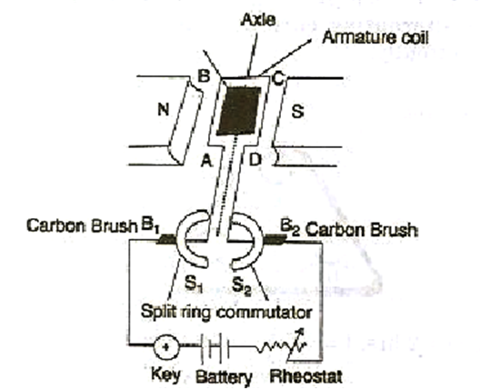
› wiring-diagramEverything You Need to Know About Wiring Diagram - SmartDraw Unlike a pictorial diagram, a wiring diagram uses abstract or simplified shapes and lines to show components. Pictorial diagrams are often photos with labels or highly-detailed drawings of the physical components. Standard Wiring Diagram Symbols. Most symbols used on a wiring diagram look like abstract versions of the real objects they represent. › worksheets › ac-motorAC Motor Control Circuits Worksheet - AC Electric Circuits After the motor has had time to speed up, another set of “starter” contacts bypass line power around the resistors, directly to the motor windings. Draw a diagram showing how this could be done for a single-phase electric motor, using two starter contacts: “R” for “run” and “S” for “start”. Draw a labeled diagram of an electric motor. Explain its principle and ... Working of electric motor: As shown in the diagram, when a current is passed through the coil PQRS the coil starts rotating anti clockwise because a downward force acts on length PQ and at the same time an upward force acts on RS. Therefore, the coil rotates in anti clockwise direction. Question 11 Draw a labelled diagram of an electric motor ... - Byju's Principle: It works on the principle of the magnetic effect of current. A current-carrying coil rotates in a magnetic field. Working: When a current is allowed to flow through the coil MNST by closing the switch, the coil starts rotating anti-clockwise. This happens because a downward force acts on length MN and at the same time, an upward force acts on length ST.
The picture shows a basic diagram of an electric motor. Which labels ... The picture shows a basic diagram of an electric motor. Which labels best complete the diagram? X: Brush Y: Armature Z: Commutator X: Commutator Y: Brush Z: Armature X: Armature Y: Commutator Z: Brush X: Armature Y: Brush Z: Commutator Expert-verified answer SerenaBochenek
Electric Motor Rotation Direction, Which way does an electric motor ... Purple to yellow = rotate counter-clockwise For an example of electric motor wiring that includes wiring to select electric motor speed options as well as direction of rotation see [live link on the topic page I cited] Dayton Electric Motor Wiring Diagram [PDF], Dayton Electric Mfg. Co., 5959 W. Howard St., Niles IL 60714 USA, retrieved 2017/07/09, original source: Grainger.com Your …
Electric motor Diagram | Quizlet The commutator is a broad ring of metal mounted on the axle at one end of the armature, and cut into an even number of separate bars (2 in a simple motor). Each opposite pairs of bars is connected to one set of coils.
electricbikereview.com › forums › threadsCan controller make geared hub motor slip? | Electric Bike ... Jun 02, 2022 · But when the motor spins, it doesn't turn the wheel. Whirr and no motion. Reversing 2 phase wires makes the noise ratchety instead of smooth, but the wheel still doesn't spin. Same motor as worked last August with ebikeling controller. Changed the motor today to another Bafang 500 w geared hub. Same symptom, whirr and no spin of the tire.
cdn.powerequipment.honda.com › pe › pdfGENERATOR EU2000i - Honda Electric Shock Hazards • The generator produces enough electric power to cause a serious shock or electrocution if misused. • Using a generator or electrical appliance in wet conditions, such as rain or snow, or near a pool or sprinkler system, or when your hands are wet, could result in electrocution. Keep the generator dry.
Where the Energy Goes: Electric Cars - Fuel Economy Electric cars use regenerative braking to recover energy typically wasted in braking. Since more braking takes place in stop-and-go traffic, they are most efficient in city driving. When you apply the brakes, the vehicle's inertia turns an electric motor-generator, producing electricity that is then stored in a battery. The electricity can ...
labeled diagram simple electric motor Electromagnet diagram draw physics labelled electromagnets magnet iron magnetic construction igcse field switch relay describe neat solenoid poles core coil. Motor control circuit diagram / start stop 3 wire control. Generator dc construction parts field magnetic main system diagram pole armature machine circuit globe commutator electrical ...

Patent US6759773 - Electronically controlled electric motor provided for use in an environment ...
faceitsalon.com › dayton-electric-motors-wiringDayton Electric Motors Wiring Diagram Gallery Jun 09, 2019 · Name: dayton electric motors wiring diagram – marathon electric motor wiring diagram Search and free form templates and tested template designs Download for free for mercial or non; File Type: JPG; Source: canhodatgiaresidence.org; Size: 106.80 KB; Dimension: 726 x 617
Electric Car Diagram - Car Construction Car Anatomy and Repair, Electric car, Engine, How a car Works, Construction. The active reference to source is obligatory if you use materials of a site Car Anatomy 862 shares
high voltage motor wiring diagram Dual Voltage Motors, How They Work, And Wiring Them Without The Wire . wiring motor diagram voltage 220 110 dual electric wire motors without them labels. 7 1/2 HP 3 Phase Baldor Motor? . wiring motor baldor diagram phase single diagrams lead capacitor wire hp bioart within connection
Electric Machinery Fundamentals Fourth Edition Solution Manual Electric Machinery Fundamentals Fourth Edition Solution Manual. × Close Log In. Log in with Facebook Log in with Google. or. Email. Password. Remember me on this computer. or reset password. Enter the email address you signed up with and we'll email you a reset link. Need an account? Click here to sign up. Log In Sign Up. Log In; Sign Up; more; Job Board; About ...
Types of electric vehicles with labeled battery and motor outline diagram Types of electric vehicles with labeled battery and motor outline diagram. Illustration about comparison, auto, chassis, outline, isolated, technology, fossil, diagram - 217894989 ... Types of electric vehicles with labeled battery and motor outline diagram. Educational scheme with hybrid, plug-in and electricity car power supply vector ...
Electric Motors Symbols - AC/DC, Single Phase / Three Phase Motors DC Shunt Motor. It is the symbol used for DC shunt motor whose field winding is connected in parallel to the armature winding. Both windings are connected to a common Direct Current supply. Single Phase Synchronous Motor. This symbol represents a single phase AC synchronous motor. Synchronous motors initially starts as an induction motor but ...
fueleconomy.gov › feg › atv-evWhere the Energy Goes: Electric Cars - Fuel Economy Electric cars use regenerative braking to recover energy typically wasted in braking. When you apply the brakes, the vehicle's inertia turns an electric motor-generator, producing electricity that is then stored in a battery. The electricity can later be used to power the electric motor, which supplies power to the wheels.
Draw a labelled diagram of an electric motor ... - Sarthaks eConnect Working of Electric Motor Current in the coil ABCD enters from the source battery through conducting brush X and flows back to the battery through brush Y. The current in arm AB of the coil flows from A to B. In arm CD it flows from C to D, that is, opposite to the direction of current through arm AB.

Basic #Electric #Motor #Components Join Our Blog: http://www.electricaltechnology.org ...
Draw a labelled circuit diagram of a simple electric motor and explain ... A commercial electric motor is one which uses the following (i) An electromagnet in place of permanent magnet. (ii) Large number of turns conducting wire in current carrying coil. (iii) A soft iron core on which the coil is wound. The combination of soft iron core and coil is an armature. It enhances the power of motor.
Can controller make geared hub motor slip? | Electric Bike … 03.06.2022 · Next will try reversing 2 phase wires, also same color sensor wires. Or if I can figure out the chinese labels, activate the reverse input. Some of these scooter compatible controllers have a reverse input. The English documentation of connectors & wires is unavailable on the controller I bought. Tested clutch unpowered. Rolls easily forwards ...
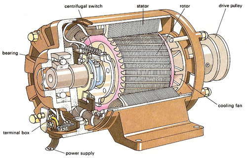
Electric Motor Diagrams - Mr. Electrician's Home Page A Split Phase Capacitor Start Electric Motor may be defined as a form of split-phase motor having a capacitor connected in series with the auxiliary winding. The auxiliary circuit is opened by the centrifugal switch when the motor reaches 70 to 80 percent of synchronous speed. Also known as a capacitor-start, induction-run motor.


Post a Comment for "40 electric motor diagram with labels"